Is your home PEMF (Pulsed Electromagnetic Field therapy) device a polite guest or a noisy party crasher in your tech-filled house? EMC (electromagnetic compatibility) is just a fancy way of saying the device plays nice with other gadgets and keeps working when your phone rings or your Wi-Fi talks.
Good shielding, solid grounding, and a smart layout act like soundproofing and doorstops for stray energy. They help the therapy stay steady and keep your neighbors' gear quiet. Here’s what homeowners need to know about emissions, immunity checks, simple shielding tips, and the main standards to watch so your PEMF setup is safe and reliable.
Emissions are unwanted radio signals your device can leak out. You might notice static on speakers, slow Wi-Fi, or your garage opener acting up. Think of it like a clock ticking too loudly in a quiet room.
Immunity testing checks whether the PEMF device keeps working when it meets outside electrical noise. Tests include ESD (electrostatic discharge) and radiated immunity checks, for example IEC 61000-4-2 (ESD testing) and IEC 61000-4-3 (radiated immunity testing). These tests make sure a burst of energy from a phone, a storm, or other gear won’t knock the device offline.
Simple shielding tips you can use at home:
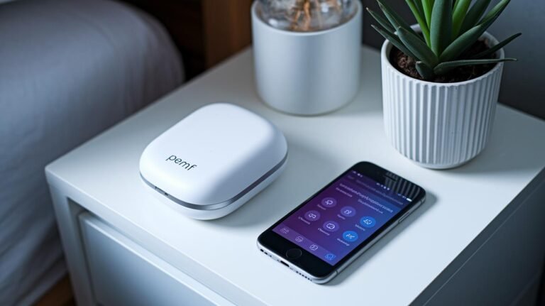
- Keep distance. Place the PEMF unit a few feet from Wi-Fi routers, baby monitors, and TVs. Distance matters.
- Use a metal enclosure or grounded plate under the device if the manual allows it. Metal helps block stray fields.
- Add ferrite beads to power and signal cords (they're little clamps that reduce high-frequency noise). Oh, and here’s a neat trick: clamp one on the power cable near the wall outlet.
- Route power cords and signal cables separately, and keep them short. Tangled cords invite trouble.
- Plug the device into a properly grounded outlet. If you’re not sure, get an electrician to check.
Standards and labels to check before you buy or install:
- FCC Part 15 (U.S. rules for radio emissions) – makes sure the device won’t interfere with other electronics.
- IEC 60601-1-2 (medical device EMC standard) – important if the device is sold as medical therapy.
- CE mark (shows conformity to European safety and EMC rules) if you’re buying from overseas.
- Ask the maker for test reports or certificates. Don’t just trust a label, look for the paperwork.
If you want peace of mind, ask the manufacturer for EMI/EMC test reports or have a qualified installer check grounding and placement. Relax. With a few simple steps your PEMF gear can be a calm, helpful guest instead of a noisy party crasher. Have you noticed any interference around your device?
EMC Compliance Essentials for Home PEMF Devices
Home PEMF device electromagnetic compatibility (EMC) means the device won’t cause harmful interference and won’t fail when other electronics are nearby. PEMF (Pulsed Electromagnetic Field therapy) devices for home use need tight limits on what they emit and solid immunity to outside electrical noise. Think of it as keeping your device polite and sturdy around other gadgets.
Emission limits cover both radiated energy (signals traveling through the air) and conducted energy (noise on wires). Immunity testing makes sure the unit keeps working when a phone rings, a router transmits, or a neighbor’s gadget switches on. Have you ever had your speakers crackle when a phone buzzes? That’s the kind of problem EMC aims to stop.
Good grounding and single-point chassis bonding are basics for reliable EMC. Grounding is like a drain for stray energy; tie metal parts to one common point and you cut down noise and stray currents. Those steps make it less likely your PEMF device will annoy other gear or be upset by it.
EMC rules connect directly to standards and regulations. In the U.S., FCC Part 18 covers unintentional radiators (devices that might emit energy). For the EU, CE marking for medical devices ties into the EU Medical Device Regulation, and RoHS limits certain hazardous substances (like lead or mercury). IEC 61000-6-3 sets residential emission expectations where people live and sleep (quiet neighborhoods, basically).
Start EMC work early in design and you’ll save headaches later. Layout choices, shielded enclosures, and proper cable terminations are like building soundproofing for the electronics, they cut the chance of failing radiated emission tests. If you plan for EMC from day one, homeowners get steady therapy with little risk of upsetting other devices.
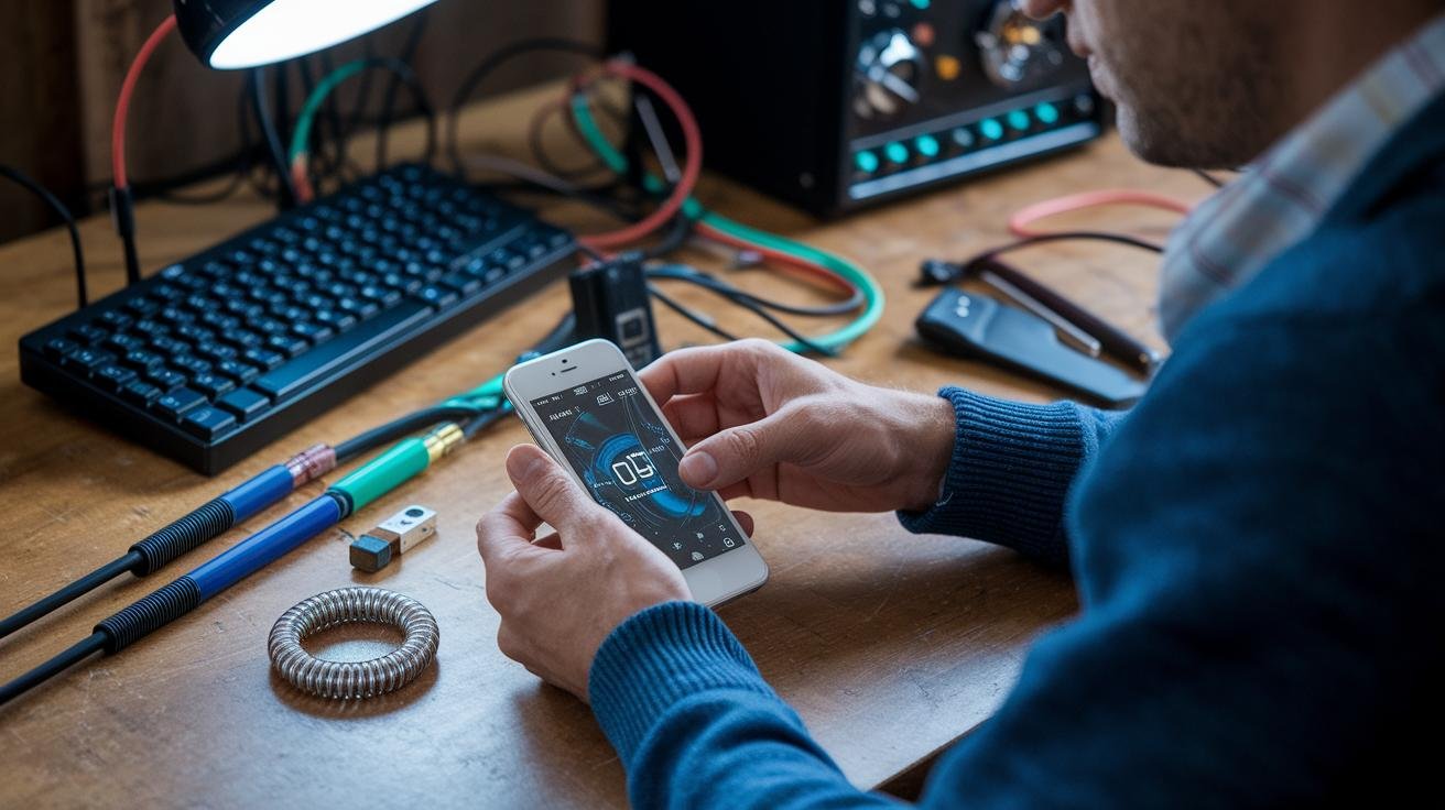
Want a quick, practical check? Measure radiated fields with a spectrum analyzer (a tool that shows frequencies and signal strength) and run simple immunity trials by placing a phone, Wi-Fi router, or switching power supply near the unit. These low-cost steps boost your odds of passing FCC Part 18 checks and CE marking requirements, while keeping IEC 61000-6-3 targets in sight.
Oh, and one neat trick: try a single-point grounding test early. It’s a small step that often reveals big problems. Next, if things look good, move to full lab testing for certification.
Shielding Materials and Applications for Home PEMF Devices
Start by matching the shielding to the kind of fields you need to tame. PEMF (Pulsed Electromagnetic Field therapy) devices can give low-frequency magnetic fields or higher-frequency electromagnetic waves, and each needs a different approach. Where do fields sneak out? Seams, vents and cable openings are the usual suspects. Think of shielding as choosing the right coat for the weather.
Mu-metal for low-frequency magnetic fields
Mu-metal is a soft alloy with extremely high magnetic permeability (it guides magnetic fields instead of blocking them). Picture it like a thick forest that redirects magnetic lines away from sensitive parts. Use thin mu-metal pieces around small coil assemblies or inside layered enclosures when low-frequency fields matter most. Note: mu-metal costs more, and it needs final annealing (a heat treatment) after shaping to keep performance.
Metalized fabric for RF comfort and flexibility
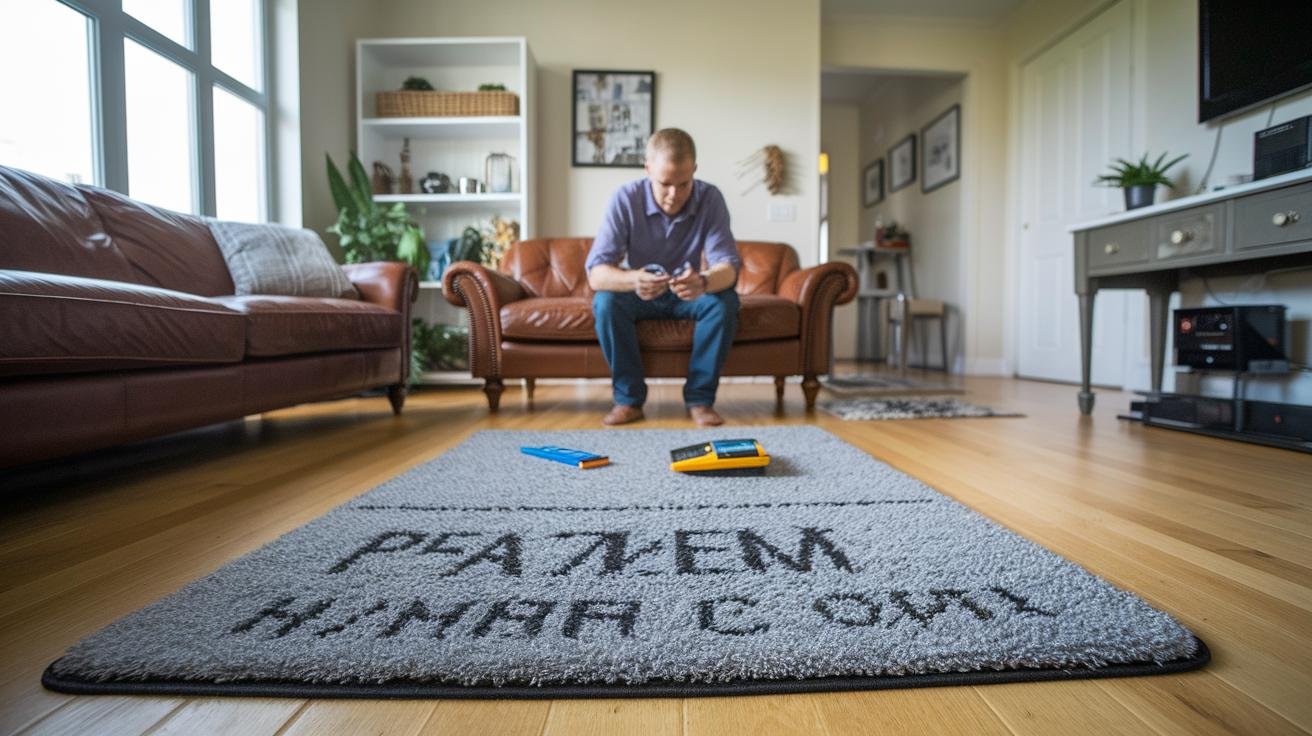
Metalized fabrics have silver or copper plating and feel like a light, conductive blanket. They block radio-frequency (RF) and high-frequency (HF) noise while staying breathable and soft. These fabrics work great under therapy mats, inside canopies, or as removable covers when you want comfort without a heavy metal box. Oh, and they’re easy to cut and sew if you need a custom fit.
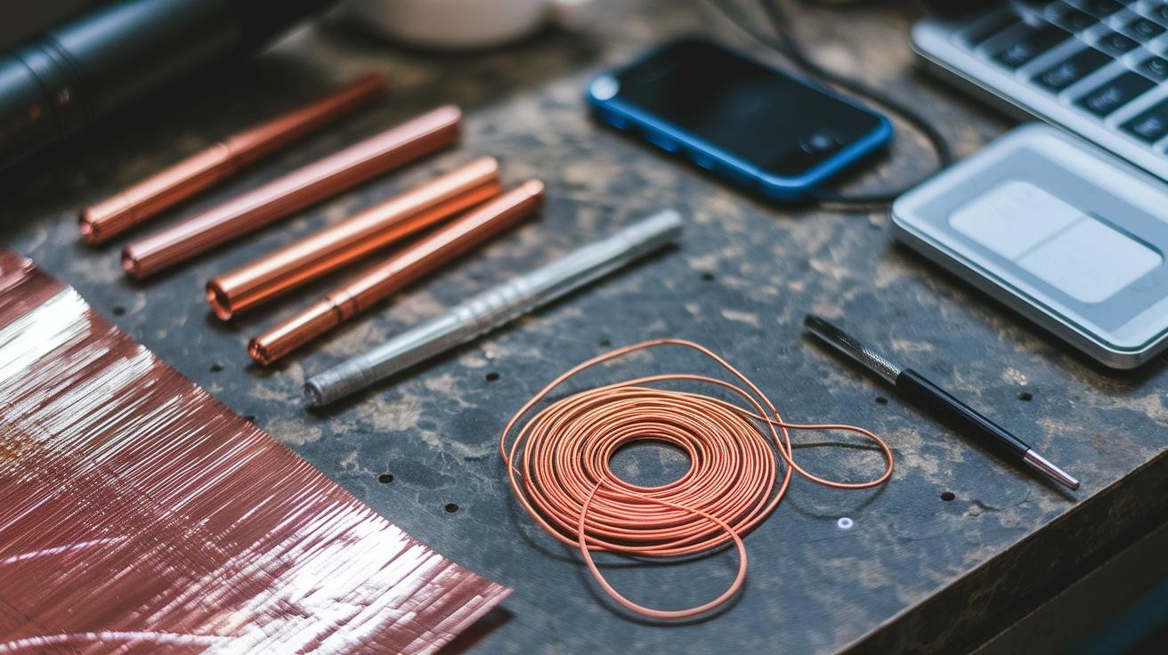
Copper foil for targeted attenuation
Copper foil is a simple, effective barrier for specific frequencies, often giving 20 to 40 dB of attenuation if installed continuously. Lay foil with 1 to 2 cm overlap (about 0.4 to 0.8 inches), seal seams with conductive tape or solder, and bond the foil to the chassis to prevent little leaks. Small gaps ruin performance, so continuous overlap and good seam sealing are key.
Conductive gaskets and cable feedthroughs
At every seam, door or connector use conductive silicone or knitted-wire gaskets to keep continuity all the way around. These gaskets stop pulsed fields and make sure the enclosure stays electrically continuous where cables pass through. For cable shields, use proper backshells and feedthrough fittings so the shield doesn’t stop at the chassis edge.
How to combine materials for best results
Match thickness and placement to your device’s emission profile. For strong, low-frequency magnetic fields, favor specialized alloys like mu-metal. For broadband RF, combine metalized fabric and copper foil, add good gasketing, and tie everything to a single common ground point on the enclosure. Test for leaks at seams and cable junctions, then fix the worst spots first.
Practical tips for home setups
Start by measuring or estimating the device frequency and locating likely leak points. Use a mix of materials rather than one perfect solution. Keep comfort in mind if the device is used on a body or bed; metalized fabric can help. One neat trick: temporarily clamp foil patches over suspected leak spots and see if readings drop before you commit to a permanent fix. Relax. Small changes often make a big difference.
Enclosure Design & Sealing
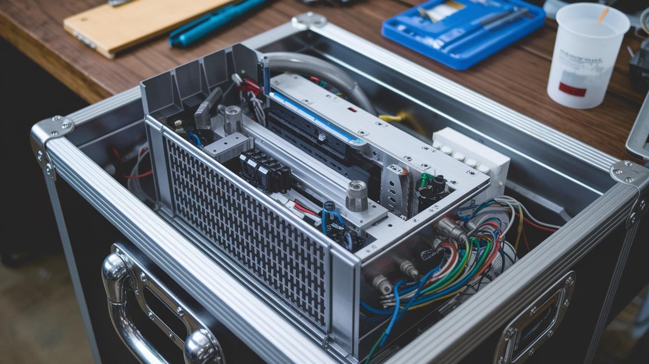
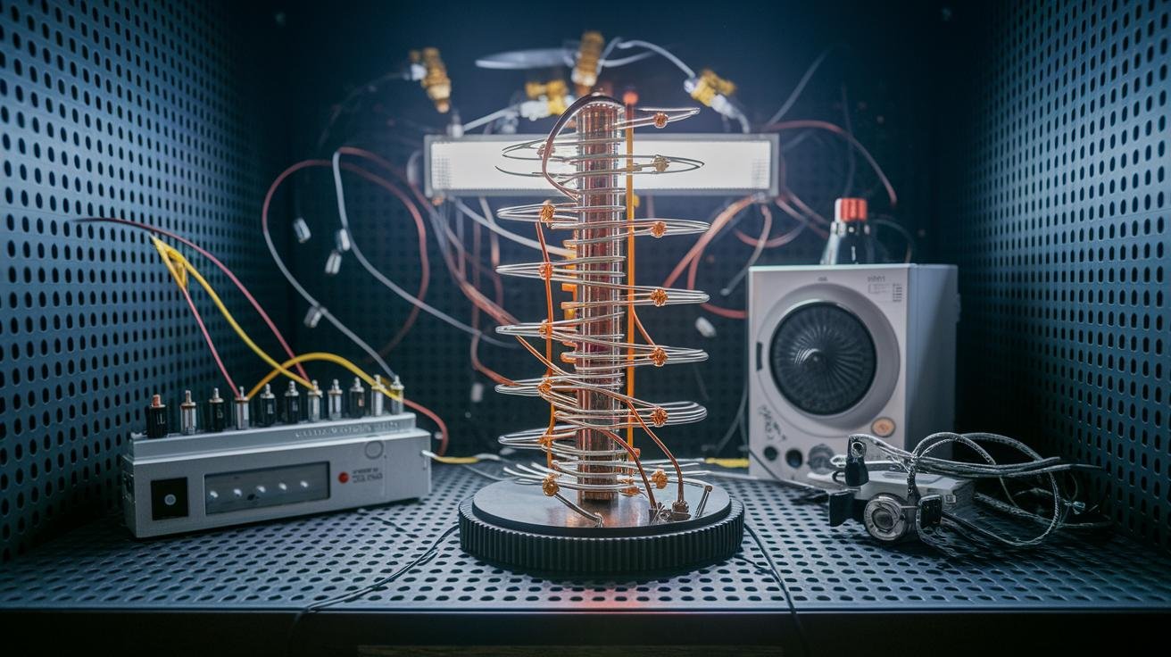
Start by making coil compartmentalization and internal shields the top priority. Give each active coil its own metal compartment or a local shield to keep stray fields contained and make troubleshooting easier. Think of each coil like a small campfire – give it a metal chamber so stray fields stay put.
Use labyrinth-style seams to stop straight-line leakage. Offset seams and create stepped paths so fields can’t take a direct route out of the enclosure. It’s like forcing air through a zig-zag hallway instead of a straight door.
Route low-frequency magnetic flux with soft-steel return plates (low-carbon steel) placed near the coils to guide flux back into the chassis and away from sensitive electronics. Put the plates close enough to steer the flux, but outside the winding area so cooling and access aren’t blocked. That way you guide the field home without trapping heat.
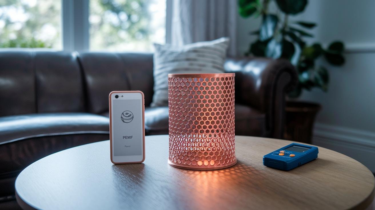
Provide airflow for cooling while still blocking RF (radio frequency) energy. Options include honeycomb vents, conductive mesh filters, or baffle ducts sized for your device’s frequency band. Place vents well away from active coils and cover openings with grounded conductive mesh mounted over a conductive plane so air passes but RF is shunted to the chassis. Keep vents at least 6 inches (15 cm) from coil edges and use a grounded plane underneath.
Practical enclosure checklist
- Compartmentalize each coil; add local internal shields where possible.
- Arrange seams as labyrinths; avoid straight-line openings.
- Add soft-steel return plates adjacent to coil areas for low-frequency flux routing.
- Use honeycomb vents, conductive mesh filters, or baffle ducts rated for your device frequency.
- Locate vents away from active coils; cover with grounded conductive mesh over a conductive plane.
- Verify performance with near-field probes (small sensors used close to the enclosure to map fields) in addition to spectrum analyzer scans.
Test with near-field probes to find leaks and fix the worst spots first. Have you tried mapping the field while running the device? You’ll spot hotspots fast.
Grounding and Cable Shielding Techniques in Home PEMF Systems
PEMF (Pulsed Electromagnetic Field therapy) gear works best when stray currents and cable antennas are tamed. You know that faint hum or buzz you hear when a device is nearby? That’s what we want to quiet. Think of a well-grounded, well-shielded system as a calm room where the therapy can sing, not shout.
Start with a dedicated equipment grounding conductor sized per NEC (National Electrical Code). Tie the chassis to that ground at a single, low-impedance point to keep loop area and circulating currents down. Use a wide bonding strap or a short copper braid instead of a skinny wire , a broad strap is like a highway for return currents, and it cuts inductance better. Make the bond mechanically solid and, if you can, plated so it resists corrosion over time.
For low-frequency gear, single-point chassis bonding is the usual practice because it limits currents from mains harmonics and coil switching. Add an equipotential bonding bar near the power inlet so all shields and returns meet at one spot. This keeps everything at the same potential and reduces surprise noise paths.
Shielding for home units can be braided jackets, foil-over-braid constructions, or properly routed twisted pairs for signal lines. Keep power and signal runs away from coil leads and sensitive circuitry. Route cables along the chassis, not across it, and avoid big loops that act like receiving antennas. Small touch: a shield is like a coat for the cable , snug and continuous works best.
Terminate shields with 360 degree continuity at the connector backshell or with a grounded cable gland. Use a soldered or crimped drain wire to the backshell so the shield doesn’t stop at the connector edge. For feedthroughs, conductive gaskets and plated feedthrough rings help the shield stay continuous through the enclosure wall.
Use ferrite beads or clamp ferrites on power cords and signal lines to tame high-frequency noise. Clip them close to the device input or the connector stack to target common-mode currents. Multiple smaller clamps spaced along a cable often beat one giant ferrite for broad-spectrum suppression. Note: ferrites help the high-frequency stuff that rides on cables , they won’t block low-frequency magnetic fields from nearby coils.
Quick, practical checks you can do at home: verify shield continuity with an ohmmeter, wiggle connectors while the unit runs to spot intermittent noise, and use a clamp meter to watch cable common-mode current. Do these checks regularly so shielding and grounding keep doing their job. Oh, and here’s a neat trick , if you cured a buzz with a bonding strap once, you’ll remember it next time.
EMC Testing Protocols and Tools for Home PEMF Devices
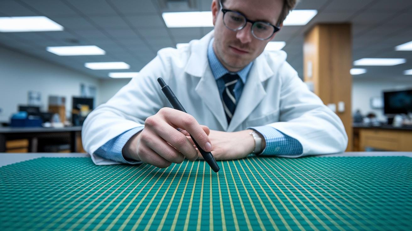
Start with a pre-compliance run. Power the unit through its normal duty cycles and log each operating mode. Put the device where there’s little outside noise so your low-frequency readings aren’t confused. Mark test points on the enclosure and at cable exits so you can repeat measurements in the exact same spots.
For radiated emissions, set the device on a non-conductive turntable in an open-area test site or a semi-anechoic chamber. Use calibrated antennas , biconical antennas for VHF and loop antennas for low-frequency magnetic fields , and an EMI receiver or spectrum analyzer to scan while you slowly rotate the unit. Record peak levels and compare them to residential limits in IEC 61000-6-3 or FCC guidance for unintentional radiators. Simple as that. Repeatable results matter.
Conducted emissions look for noise riding on power and signal lines. Put a line impedance stabilization network (LISN) between the device and the mains, then measure with an EMI receiver. Watch both differential and common-mode signatures. Test again with any accessory cables attached, since cables change how noise couples out. Think of the LISN like a gatekeeper between the wall and your device.
Immunity testing follows IEC 60601-1-2 (the medical-equipment standard). Inject EFT (electrical fast transients), apply surge events, and use electrostatic discharge (ESD) tests while you watch the device’s behavior. Also run mains voltage dips and radio-frequency immunity checks to make sure the unit keeps delivering therapy and doesn’t false-trigger or reset. You want the device to stay calm under stress.
Low-frequency checks use near-field probes and current clamps to map stray magnetic flux right around the coils. Keep the measurement setup consistent so you can track design tweaks over time. When you try gasket or shielding fixes, repeat the same setup to see real changes, not measurement noise. It’s like taking before-and-after photos with the same light.
Essential gear for a solid lab setup includes an EMI receiver, LISN, calibrated antennas, near-field probes, current clamps, and a turntable or positioner. A semi-anechoic chamber or a well-shielded room makes results repeatable and defensible if you move toward certification. Oh, and a clear test log will save you hours later.
🎁 Get a Free Wellness Gift
Enter your name and email below to receive a special wellness gift from OlyLife — absolutely free!
Quick Troubleshooting Checklist
If a PEMF (Pulsed Electromagnetic Field therapy) unit is noisy or upsetting nearby gear, this short checklist helps you find and fix the problem. Start simple, then move to measurements. Want to think of it like detective work? Good. Let’s go.
-
Map fields: sweep seams, cable runs, and the mat with a near-field probe and mark the loudest spots. Walk slow and steady so you catch sharp peaks.
Example: "Sweep the probe along the seam; a sharp spike where the probe passes means a leak." -
Isolate cables: unplug accessories, separate power and signal runs, then test again. If the problem changes, a cable is likely coupling energy into the system.
Example: "Unplug the accessory lead , if the hiss stops, that cable is coupling energy." -
Try clamp ferrites: clip ferrites onto suspect cables (power, signal, shield) and retest. Even one ferrite near the enclosure can make a big difference.
Example: "Clip one on the power cord near the enclosure; a drop in noise is a win." -
Patch seams: re-gasket joints, apply conductive tape or copper foil over seams and vents, and solder overlaps when practical. Think of it like weatherproofing a window.
Example: "Lay a copper strip over the seam and press firmly; retest for the spike to shrink." -
Wiggle connectors: run the device while gently moving plugs and connector backshells to find intermittent shield contact. Tiny movements can reveal big problems.
Example: "If noise jumps when you wiggle a plug, suspect poor shield contact." -
Measure shield resistance and common-mode current: use an ohmmeter for shield continuity and a clamp meter for shield or common-mode current. Note values before and after fixes.
Example: "Shield continuity should be near 0 ohms; a clamp meter showing suddenly high mA points to strong common-mode coupling." -
Log results: record probe spots, cable routing, ferrite placement, and measurement values so you can compare after each change. A photo is worth a thousand words here.
Example: "Photo the taped seam location and jot the probe peak so you can confirm improvement later."
Typical measurement guidance and likely causes
- Shield continuity: near 0 Ω, preferably less than 1 Ω. Much higher means poor bonding or a broken shield.
- Common-mode current: low single-digit mA is normal. Readings in the tens of mA suggest strong coupling along cable shields or a missing ground.
- Near-field probe spikes: sharp, localized spikes at seams or vents usually mean shielding leaks. Broad fields along cables point to cable-borne emissions.
Symptom → likely cause
- Radio hiss or audio buzz → probable common-mode on power or signal lines.
- Gadgets resetting or digital glitches → high-frequency radiated emissions from switching electronics or switching power supplies.
- Emission changes when touching the enclosure → missing bond or poor chassis contact.
- Emission changes when wiggling connectors → intermittent shield termination.
When to call a professional
If you can’t isolate the source with these checks, measurements show shield continuity well above 1 Ω, common-mode current stays in the tens of mA, or fixes don’t reduce near-field peaks, bring in an EMC consultant for chamber testing and root-cause analysis. Better to get help than chase a stubborn mystery.
Final Words
We covered core EMC principles, emission and immunity basics, plus FCC, CE and IEC standards.
We also explained mu-metal, conductive fabrics and copper foil, and when to use each.
Then we looked at enclosure sealing, grounding and cable-shielding practices, plus test methods for radiated and conducted emissions.
Oh, a simple cable reroute often fixes odd noise. Troubleshooting tips and periodic retesting round out the plan.
Follow these steps to reduce interference and protect device performance.
You’ll feel more confident about electromagnetic compatibility and shielding for home PEMF devices, and enjoy quieter, more restorative sessions.
FAQ
PEMF FAQ
- What is the best PEMF device for home use?
- The best PEMF device for home use balances adjustable field strength, clear safety certification, solid EMC design, and easy controls; common choices are low-frequency mats and handheld wands from trusted makers.
<dt>Which PEMF devices are FDA approved?</dt>
<dd>FDA approved PEMF devices are cleared for specific medical claims; check the FDA 510(k) database for listed models, often including bone-healing and pain-relief systems from established manufacturers.</dd>

<dt>Can I do PEMF therapy at home?</dt>
<dd>You can do PEMF therapy at home with consumer units made for domestic use; follow the manufacturer’s instructions, verify safety and EMC marks, and consult your clinician if you have implants or concerns.</dd>

<dt>Does aluminum foil stop EMF radiation?</dt>
<dd>Aluminum foil can block some high-frequency radio waves but performs poorly against low-frequency magnetic fields from PEMF; mu-metal or purpose-built magnetic barriers are more effective for those fields.</dd>

<dt>How do I shield against EMI?</dt>
<dd>Shielding against EMI uses continuous conductive enclosures, copper foil barriers with sealed seams, conductive gaskets, mu-metal for low-frequency fields, ferrite beads on cables, and careful cable routing.</dd>

<dt>What are the benefits of PEMF devices?</dt>
<dd>The benefits of PEMF devices include reduced pain, faster post-workout recovery, better sleep, and improved circulation by applying gentle pulsed magnetic fields to tissues; outcomes depend on frequency, intensity, and consistency.</dd>

<dt>Are there PEMF devices for horses?</dt>
<dd>PEMF devices for horses include large mats and heavy-duty applicators sized for equine joints and muscles, offering similar recovery and pain-relief effects with higher power ratings and robust construction.</dd>

<dt>What EMC standards apply to home PEMF devices?</dt>
<dd>EMC standards for home PEMF devices include FCC Part 18 in the US, CE marking under EU rules, IEC 61000-6-3 for residential emissions, and RoHS limits on hazardous substances.</dd>

<dt>How do I test PEMF devices for EMC compliance?</dt>
<dd>EMC testing for PEMF devices uses radiated and conducted emission checks with spectrum analyzers and LISNs, near-field probes and current clamps for low-frequency measurements, plus immunity tests like IEC 60601-1-2 in a calibrated chamber.</dd>

<dt>How do I maintain shielding integrity and troubleshoot EMI?</dt>
<dd>Maintaining shielding integrity means inspecting and re-gasketing seams, checking with near-field probes, adding ferrite clamp filters, rerouting noisy cables, and scheduling retests every 12–24 months.</dd>